Belgian Fortifications, May 1940
Written by
Bernard Vanden Bloock
[
Overview |
Deep Defences |
Border Defences |
Conclusions
]
[
Appendix A: Bunker Types |
Appendix B: Weapons |
Bibliography
]
Appendix A: Bunker Types
Belgian Light Type Machine Gun Bunker
|
Purpose
|
Help the infantry to conduct delaying actions. No prolonged
or determined defence
|
|
Design
|
Designed to sustain the impact of a single 77 mm HE
shell or sustained fire from smaller calibre weapons
|
|
External dimensions
|
300x 320 cm
|
|
Wall thickness
|
40 - 60 cm (60 cm for walls exposed to enemy fire)
|
|
Roof thickness
|
50 cm
|
|
Armament
|
One heavy machine gun
|
|
Remarks
|
One room, closed by a single steel door
|
Plans
The author drew up these plans from a half-buried
bunker located in the Ourthe valley. All light machine gun bunkers had
the same dimensions and wall thickness. Depending on the terrain, the
door could be at the back of the bunker or on either side. Here it is
on the side, at the bottom of a small staircase.
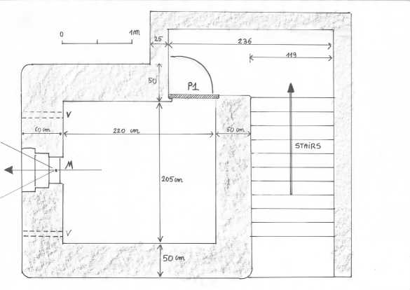
Belgian Light Type Machine Gun Bunker: Top View.
|
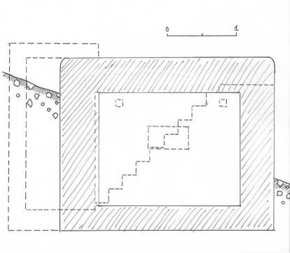
Belgian Light Type Machine Gun Bunker: Front View
|
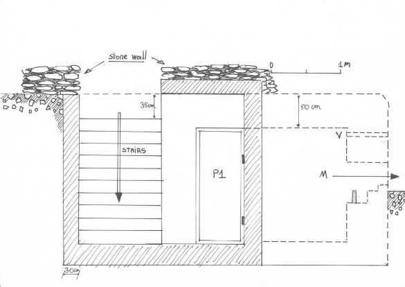
Belgian Light Type Machine Gun Bunker: Side View.
|
Belgian Medium Type Machine Gun Bunker
Medium machine gun bunkers were armed either with
one or two heavy machine guns and their actual dimensions varied accordingly.
Contrary to light bunkers, they were intended for prolonged fighting.
They all shared the set of features listed below:
|
Purpose
|
To be used as part of a battle line.
|
|
Design
|
Designed to withstand sustained 150 mm HE fire and/or
survive the impact of a single 220 mm shell.
|
|
External dimensions
|
Variable
|
|
Wall thickness
|
100 130 cm (130 cm for walls exposed to fire)
|
|
Roof thickness
|
115-130 cm
|
|
Armament
|
One to two heavy machine guns, grenade gullies for
close defence
|
|
Remarks
|
Lock-type entrance with two successive steel doors.
|
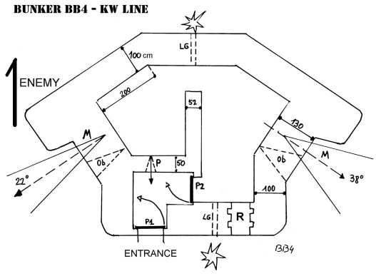
Simplified plan of a medium type bunker showing the common features
of all medium bunkers : two doors (P1, P2), grenade gullies (LG), two firing ports (M), an entry defence port (P)
and the emergency exit (R). The observations slits (Ob) are particular to the Dyle line bunkers
|
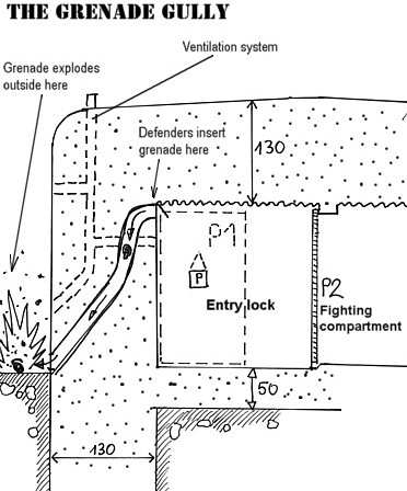
A cut view of the grenade
gully system for close defence.
|
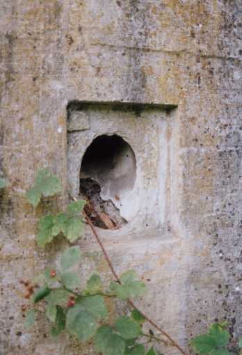
The exit of a grenade
gully. The steel shutter that sealed off the exit is missing.
|
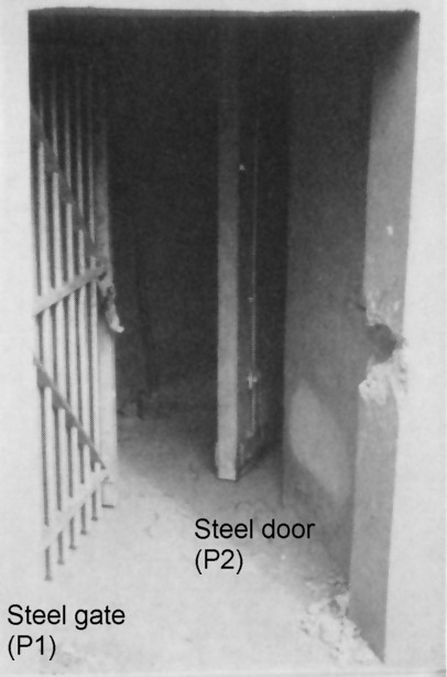
The entry lock of a medium
bunker with a steel gate (P1) followed by a steel door (P2).
|
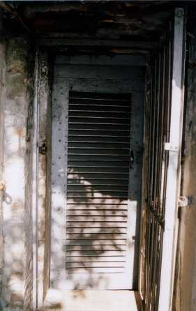
This is what the second
door looked like. The blinds were meant to improve ventilation,
a steel shutter could be fixed on the inside to seal off the door
completely if needed. This particular door is located not in a bunker
but in one of the defence blocks of Fort Battice (PFL I).
|
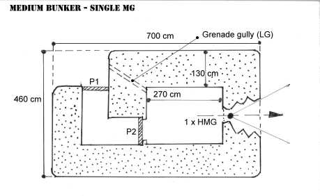
Medium Type Machine gun Bunker: Single Machine Gun Type
The single machine gun bunkers all had the same
external dimensions, i.e. 7 m x 4,60 m. The inner chamber or fighting
compartment measured 270 cm by 200 cm. The entry lock was placed to the
back of the bunker or to one of its sides, as the tactical situation required.
Medium Bunker Single
machine gun.
|
Bunker NV-16, defending
the approaches of Fort Aubin-Neufchâteau (PFL-I). The entry lock
is on the right side.
|
Medium Type Machine Gun Bunker: Dual Machine Gun Type
There are many designs here as the position of
the machine gun s relative to each other varied according to the local
tactical requirements. In some instances, the guns fired in the same direction,
in others they fired in opposite directions, and then there were many
intermediate solutions. There is really no difference with the single
machine gun bunker except in size and the presence of an emergency, crawl-through
exit sealed by a removable barrier of steel girders and bricks hidden
behind a cement covering. When the main exit was destroyed or blocked,
the bunkers garrison were supposed to remove the girders, then use their
rifle butts to knock down the brick and cement wall.
Another difference is that medium were designed
to give lateral or flanking fire, never frontal fire. You will notice
this when looking at the plans. The side of the bunker that is facing
the enemy (i.e. the top side of the image) doesnt have any firing ports,
only a grenade exit.
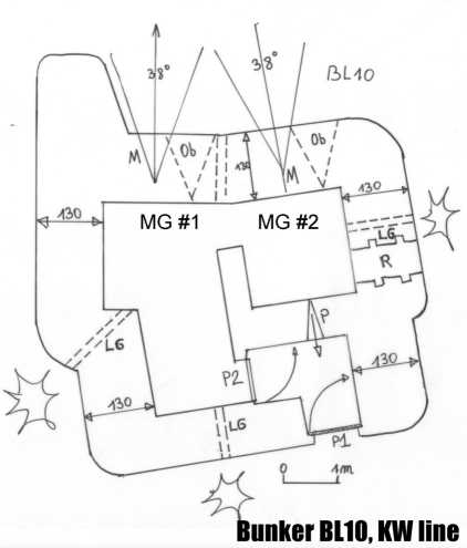
Simplified plan of a
medium bunker with both machine guns firing in the same direction.
This bunker is placed at the edge of a forest and fires into a clearing.
The enemy is likely to come from the left of the picture. Note how
the firing ports are protected from enemy fire by a large slab jutting
out of the building.
|
Virtual Visit (Medium Bunker)
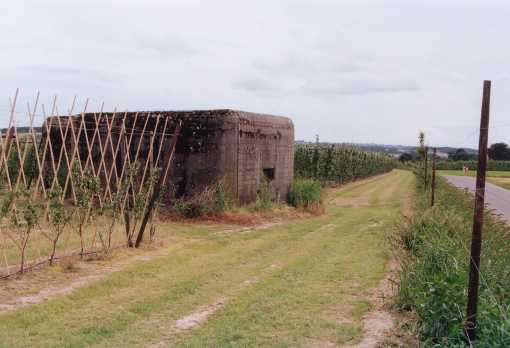
A typical KW line bunker.
Coded LW10, this one defended a bridge on the Dyle North of Wavre,
in the sector of the First British Division.
|
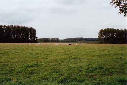
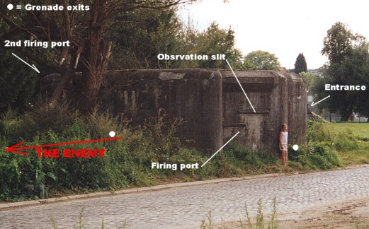
This is the field of fire
of the firing port you saw on the preceding photograph. The Dyle
runs somewhere to the right of the trees on your right.
|
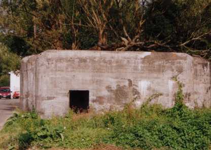
The back of the bunker.
The emergency exit is hidden by the shrubbery.
|
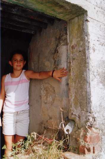
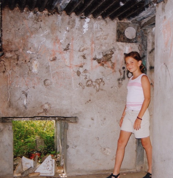
The authors daughter,
Valérie is standing in the entrance of the bunker. The wall she
is modeling is 130 cm thick. You can see one of the hinges of
the entry gate.
|
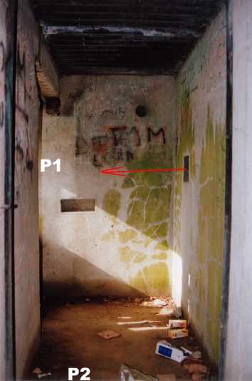
Inside the frame of the
steel door (P2). The gate (P1) is to our left. Note how it
is defended by a rifle port on the opposite wall (P).
|
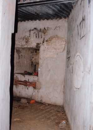
Valérie, inside the steel
doors frame, is now entering the first machine gun chamber. Emergency
exit is to the left.
|
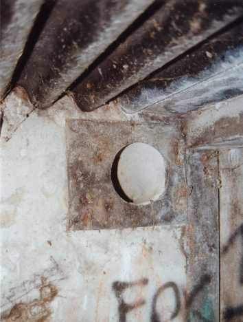
A close up on the opening
of the grenade gully.
|
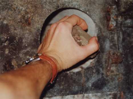
Yours truly demonstrating
how a grenade is inserted in the gully. This one would have exited
at the back of the bunker, between the entrance and the emergency
exit.
|
Standing just inside the
second door, looking into the first machine gun room. You can make
out the (sealed) firing port to the left.
|
A close up view of the
machine gun port #2. The rusted fixtures are whats left of
the Chardome gun mount.
|
Anti-Tank Bunkers
Anti-tank bunkers were either modified machine
gun bunkers or large works specially designed to deal with a particular
tactical situation. For the purpose of this article, we will call the
former small and the latter large. Most anti-tank bunkers were concentrated
in the PFL, but there were a few on the North-eastern border, in the Ardennes
and along the Southern approaches to Brussels.
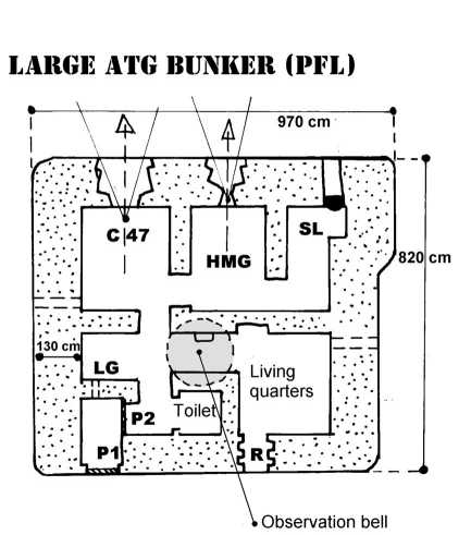
All bunkers were armed with one 47 mm anti-tank
gun. In most instances, this was the Belgian C 47 D gun but some bunkers
were fitted with the French APX2b tank turret. Large bunkers were armed
with a 47 mm, one heavy machine gun, one searchlight and in some cases,
an armoured observation cupola. Small anti-tank bunkers were
armed with just the anti-tank gun. Both types sported some of the features
of the medium Machine gun bunker (same wall and roof thickness, entry
lock with two doors, grenade ports).
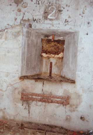
Casemate Mont, a large anti-tank gun bunker of the PFL - I. It barred
the road from Theux to Louveigné where it passed the small village
of Mont.
|
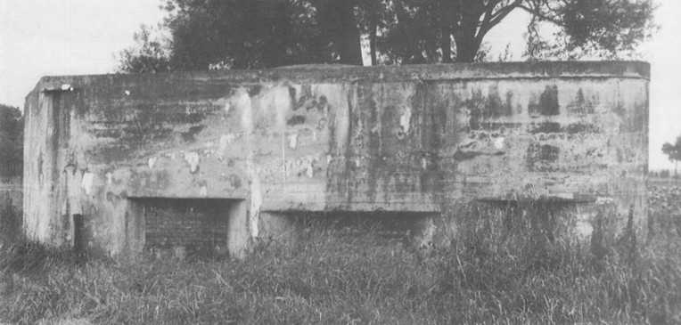
Bunker A23 defending the
Dutch border forward of the BocholtLanaken canal. This large anti-tank
gun bunker was located in Grevenbricht. The large firing port in
the centre is where the 47 mm anti-tank gun was located.
|
Artillery Observation Bunkers
Artillery being an indirect fire weapon, its effectiveness
is largely dependent on the presence of forward observers who can identify
targets and direct the guns fire. Every Belgian artillery fort had a
number of artillery observation posts attached to it. They were the eyes
of the fort. Some of those posts were mobile; others were installed in
bunkers. There was no standard design for artillery observation bunkers.
Most were modified machine gun bunkers retro-fitted with an armoured observation
cupola. Artillery observation bunkers will be described in more detail
in the Forts article.
|